
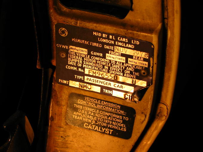
1979 Triumph Spitfire - purchased in 1982 from the original owner in Greenville, SC.
Current Odometer Reading - 72322 miles
My first automobile was a 1970 Ford LTD. As the frame began to rot, I began searching for a replacement. In my search, I looked at a beautifully restored fire engine red '57 Chevy with button-tuck interior, and a '67 Chevy Camero that spewed oil and smoke. My father spotted the Spitfire at a Mall in Greenville, SC and after looking it over and taking a quick test drive, I was hooked. Shortly thereafter, my father purchased a 1976 Spitfire and my brother purchased a 1973 Spitfire.
The Spitfire was my primary mode of transportation until 1985. After being late to work one too many times, I bought a new 1984' Pontiac Fiero. Since then, I have had a love hate relationship with the Spitfire. When it wasn't running, I wanted to sell it. Once I fixed it, I wanted to keep it... then it broke again and the whole cycle began over. For several years, I had a secret method for starting the Spitfire. This involved placing a voltmeter across the coil and shorting the leads with a screwdriver until the voltmeter indicated 9 volts. It was then ready to start. This "feature" prevented it's theft on more than one occasion.
The Spitfire has followed me from North Carolina to South Carolina, Mobile and Birmingham, Alabama. It's last voyage was in 1998 when I took my 3-year old daughter for a ride. After 5 minutes out, the engine stalled and the Spitfire breathed its last breath. It was towed back to my garage where it has continued to gather dust. This is the first restoration I have performed on it and it is long overdue.
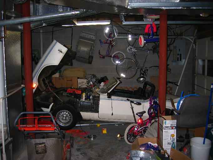
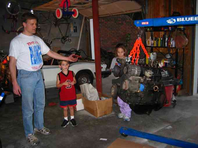
Spitfire hidden behind Toys, lawn mowers and tricycles.
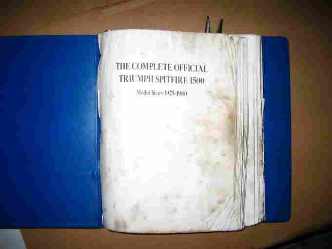
The Complete Official Triumph Spitfire 1500 Shop Manual - Essential for any serious Spitfire work.
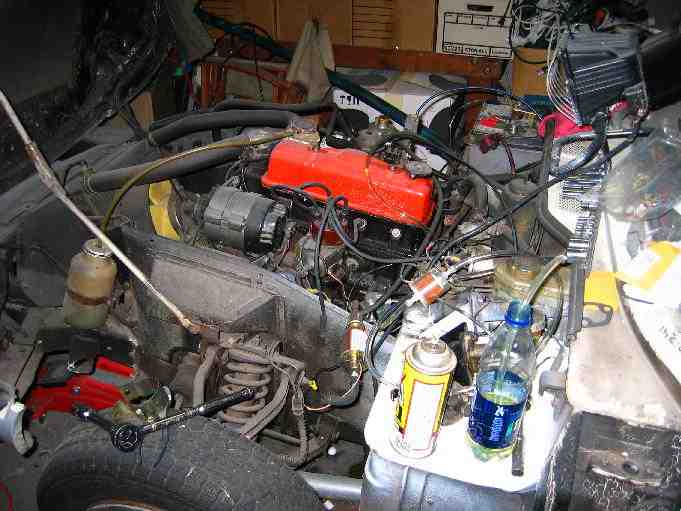
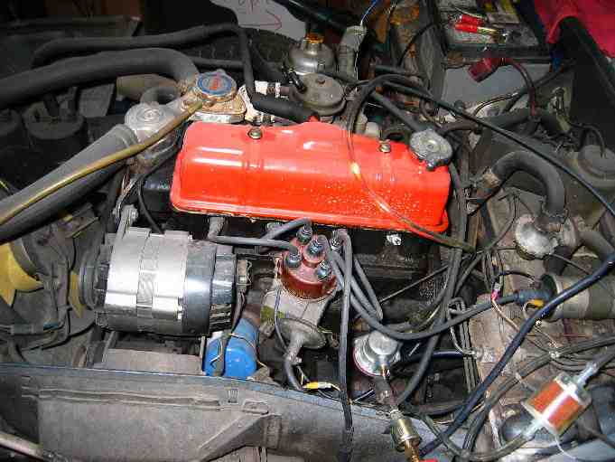
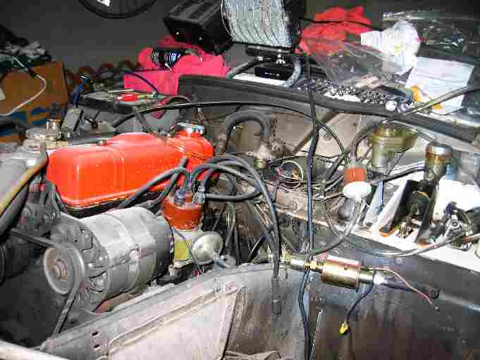
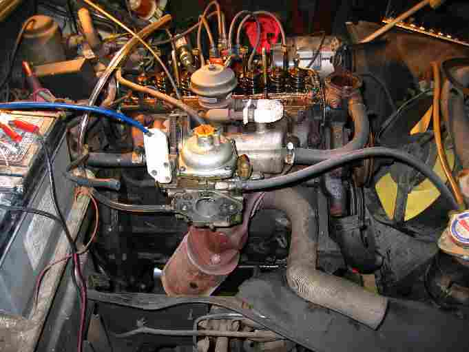
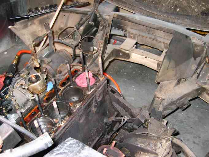
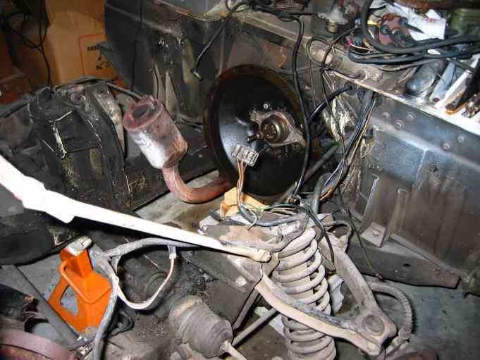
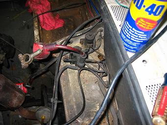
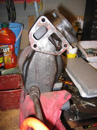
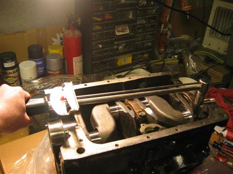
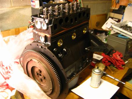
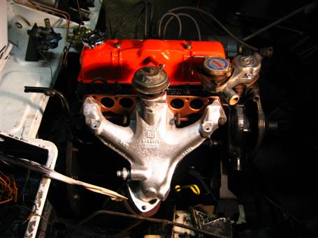
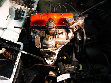
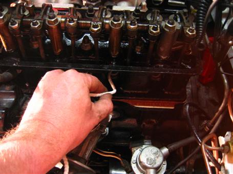
Left-hand view of engine. Notice the water bottle filled with gasoline. This was used for exploratory diagnosis. I was getting spark but no fuel. After replacing the original mechanical pump with an electric pump, fuel was still not making it to the spark plugs. In order to eliminate the gas tank, fuel filter, fuel lines and fuel pump, I set this up with clear hose. After many attempts, fuel was not moving. After cleaning the carb, I could visibly see fuel flow but the Spark plugs were as dry as a bone.
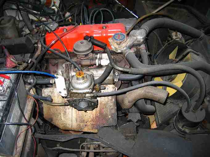
Close up of distributor cap wiring for later reference.
Closeup for later reference.
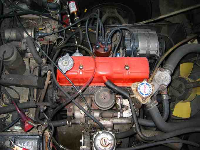
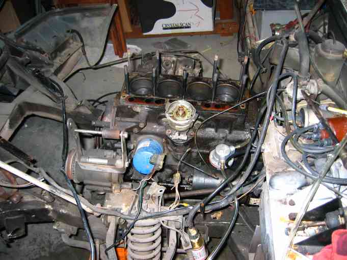
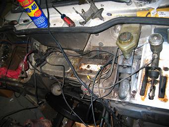
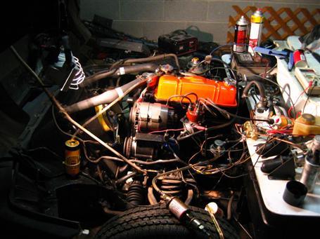
Top view
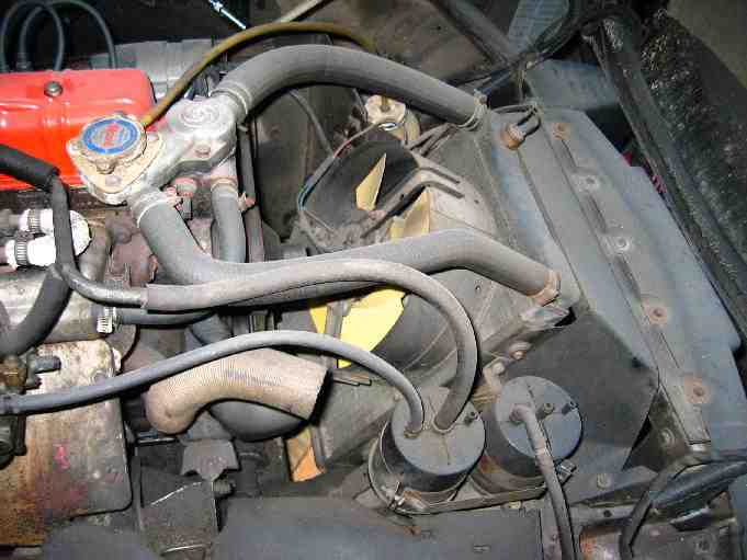
Radiator
Alternator
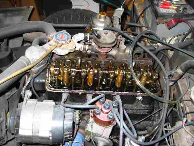
Time to get our hands dirty... Valve cover removed!
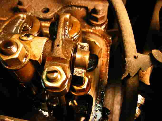
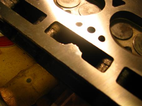
This rear #4 rocker arm pedestal was broken and was lodged in with the adjacent push rod.
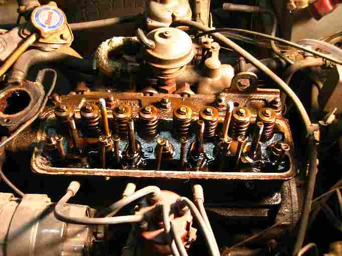
Rocker Arm Removed...
Heat shield and Water pump removed...

Remove push rods and store in cardboard to keep in order...
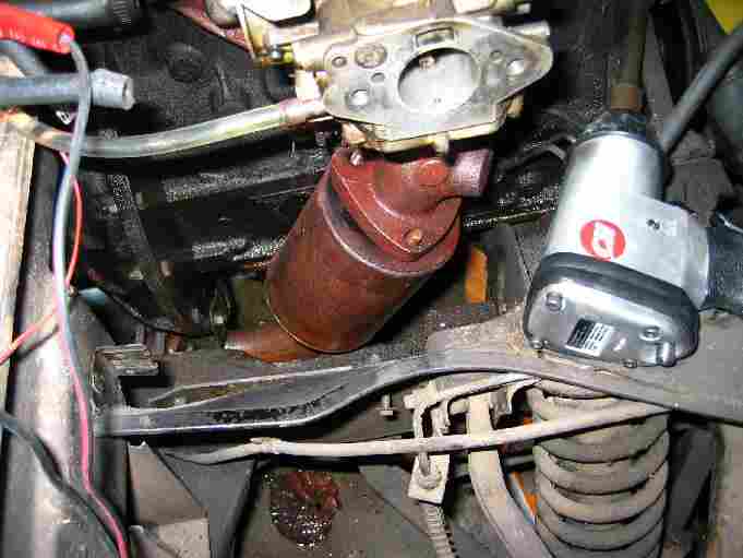
Catalytic Converter removed with lots of WD-40 and an Impact Wrench. I wish I had air tools when I did the clutch job!! The fastening nuts were 14mm which is very unusual. Most bolts are almost always 1/2" or 9/16". Maybe they just rusted down to metric size :-)
Remove the cylinder head nuts and bolts. I wrapped them in wire to keep them in order for refitting.
This picture doesn't do the effort justice. Removing the cylinder head took almost an hour of cussing, tapping with wooden mallets, cussing, rocking the head back and forth, cussing....
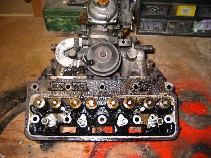
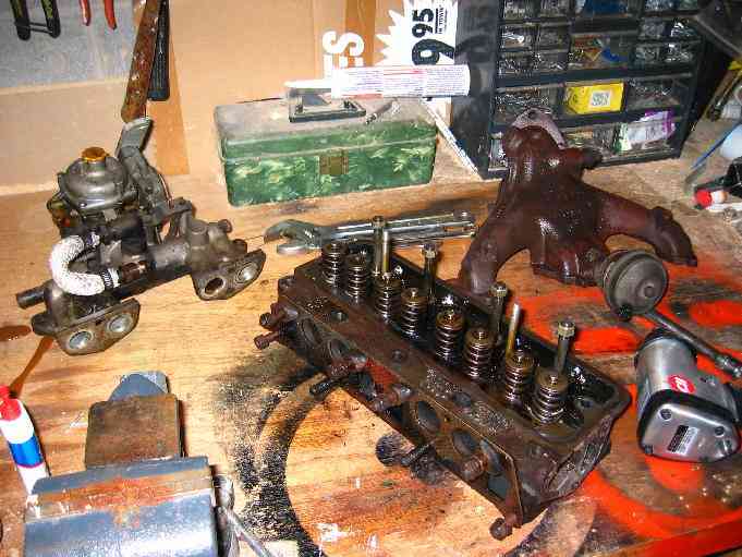
Removed Cylinder head with intake manifold and SU carb.
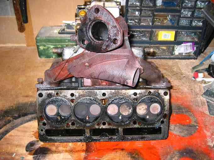
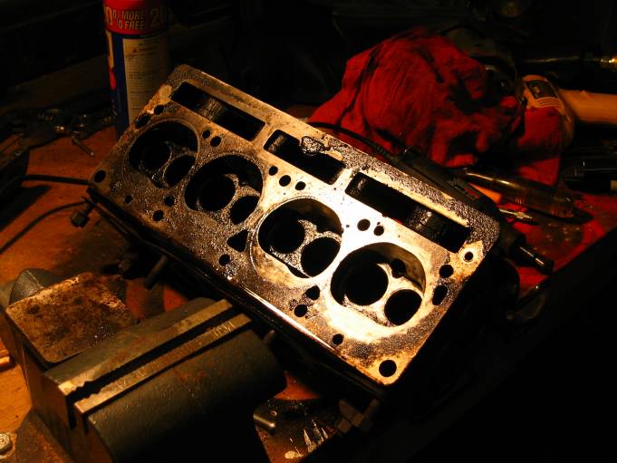
Bottom of Cylinder head and exhaust manifold. Note the missing exhaust gasket.... This has been missing since the catalytic converter caught fire. I always suspected the mechanic forgot to put this on... He was the last "professional" mechanic to ever work on the Spitfire and that was way back in 1985.
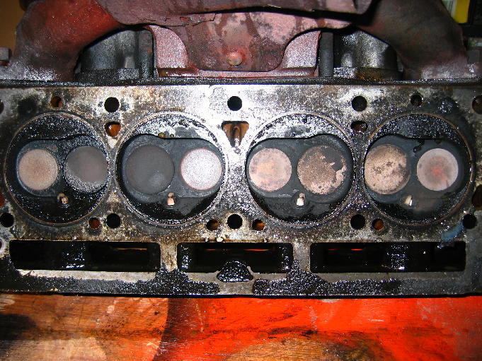
Lots of carbon deposits...
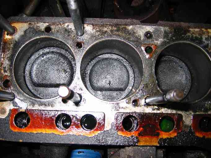
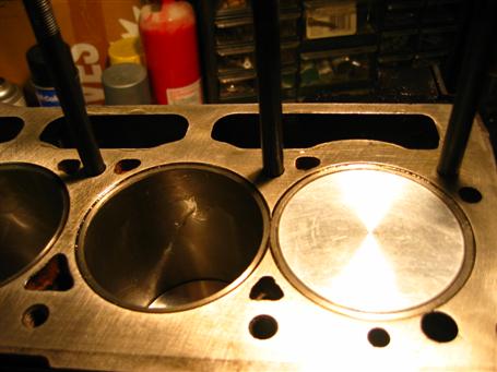
More Carbon on the pistons...
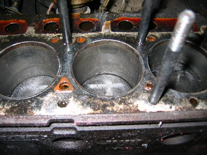
But I don't see any gouges or scrape marks on the piston walls...
I got a lot of advice from the guys on NASS - North American Spitfire Squadron so tonight I am pouring through the manual and Victoria British catalog. They have pointed out the obvious... that I am already in deep so I might as well go ahead and perform a major overhaul. They also suggested that it will be easiest to put the cylinder head back on the engine block and hoist the whole engine assembly. My big decision now is to decide on a high-performance overhaul or go for stock originality.... but in the meantime, I removed the intake and exhaust manifold. The gasket was blown between the exhaust ports of #2 and #3.
Check out the NASS newsgroup:

There is a gap in time but I ordered the Spitfire Comp Preparation Manual and looked through catalogs trying to get an idea of how deep I am getting in.
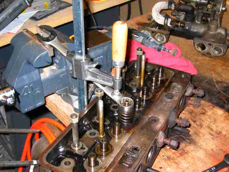
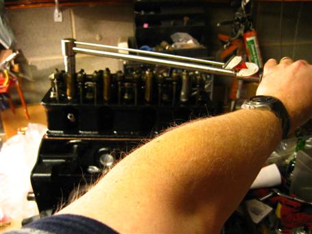
I didn't have a valve spring compression tool so I improvised using a wood vise, a vise and a 3/4" wrench. It works like a champ!
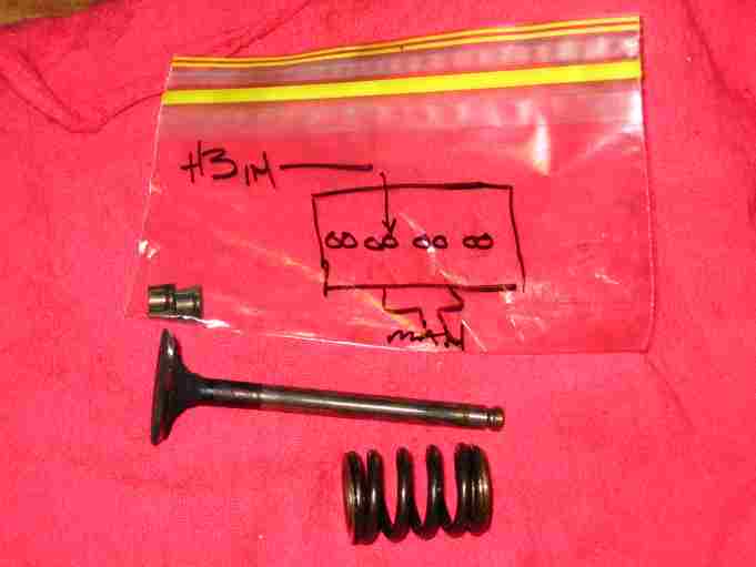
Store and label for refitting.
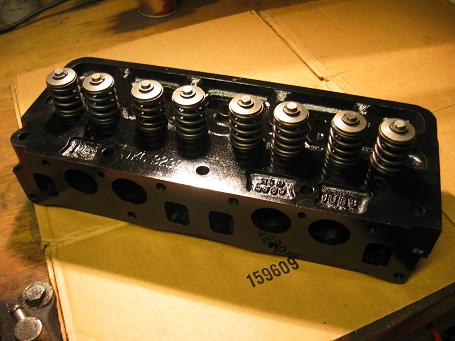
Polishing the head using a Dremel Tool and brass brush. Note all the crud...
Continued polishing the cylinder head. My wishlist for the rebuild:
1. Weber Carbs
2. Kent Racing Camshaft
3. Bore out pistons 0.030"
4. Replace all bearings and seals
5. Add an Oil Cooler
6. Upgrade Shark electronic ignition to Mallory
Prepared for engine hoisting by removing all ancillary parts. Put the Cylinder Head and hoist hooks back on.
Removed Radiator
Removed Distributor sensor.
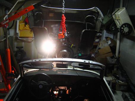
The big day! Rented a Bluebird Cherrypicker Engine Hoist.
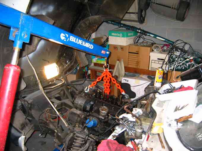
Hooked in place and ready to lift
... and 30 seconds later, the engine is removed! :-)
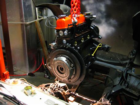
Clutch with less than 1000 miles since rebuild.
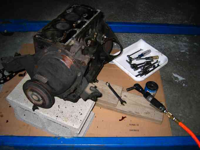
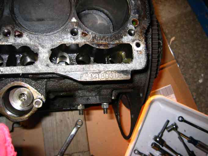
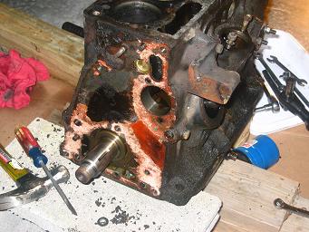
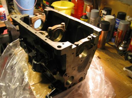
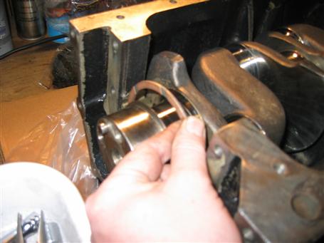
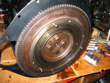
Block in process of stripping. Now to figure out how to get the crankshaft flywheel off...
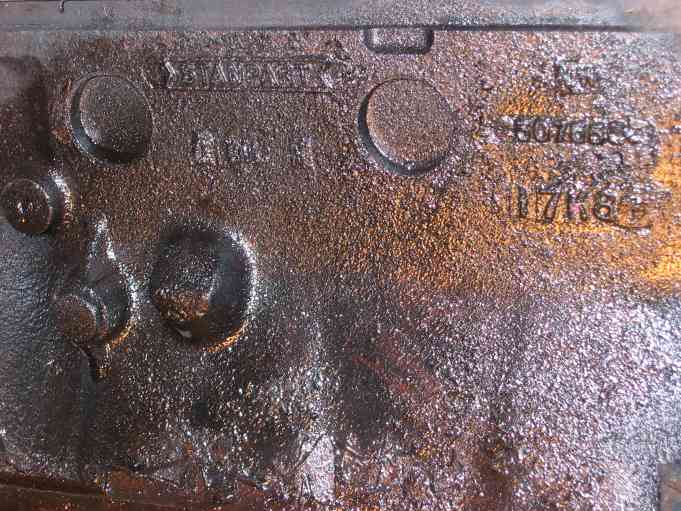
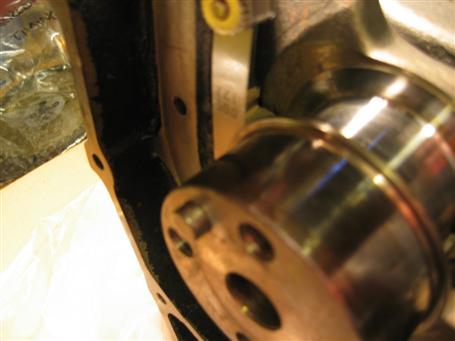
Interesting marks
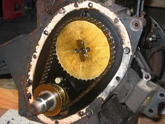
Timing Gear cover removed.
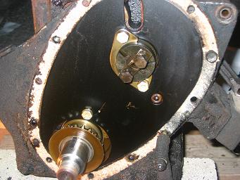
Sprocket and chain removed
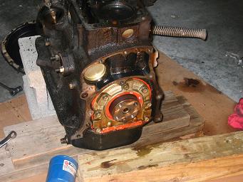
Rear Engine Plate removed. Rear oil Seal housing exposed.
Front Engine Plate removed.
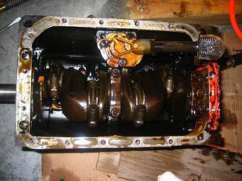
Flip over the engine and remove the Oil Pan.
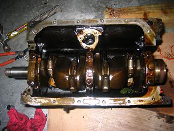
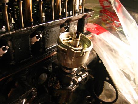
Oil Pump removed.
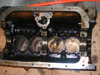
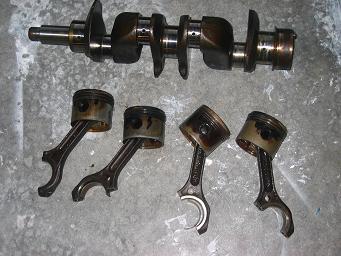
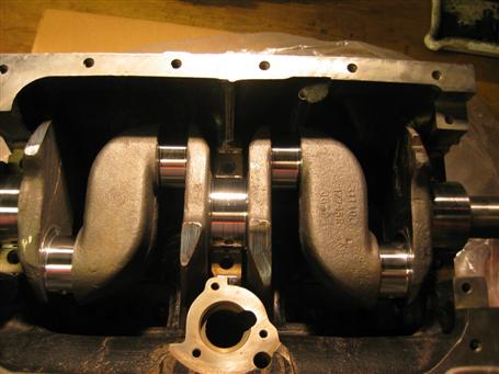
Removed the crankshaft and pistons. The crankshaft looks ok and the the bearings were not terribly scored. The rings don't look too bad for an engine with 72,000 miles. I called my mechanic and got a good reference for a competent machine shop with experience with Triumph motors. Plans are to magnaflux, bore, crankshaft, and replace freezeplugs.
It appears that progress is slowing but actually it is moving along in smaller increments. Scraping battery acid isn't as grandiose as pulling the engine but it does take time. The Spitfire has become an onion... as I peel back a layer, another layer appears. So far, I haven't run into anything too difficult. Just things that I want to fix while I have the engine pulled. I also got parts to fix my pressure washer which will come in very handy, especially washing all the grease and grime from the frame in the engine bay.
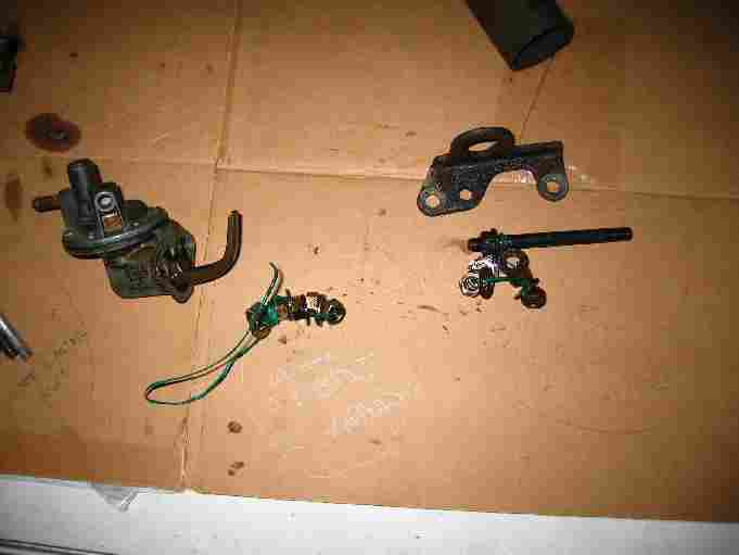
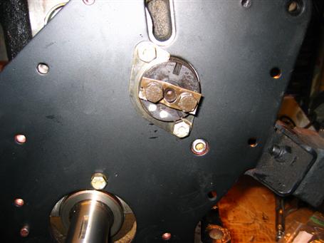
Starter Solenoid and Washer pump. Note Battery well. Lots of acid...
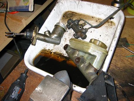
Heater Valve removed.
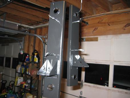
I checked the Clutch and brake operation today and both are in need of repair. Add a Clutch Master, Slave and Brake Master Cylinder rebuild kit to the long list of parts. I also went ahead and pulled the master cylinder mounting brackets. The paint below was gumming up from years of spilt brake fluid. The Pneumatic grinder with brass brush works much better than sandpaper and elbow grease for removing old paint and rust!
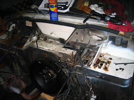
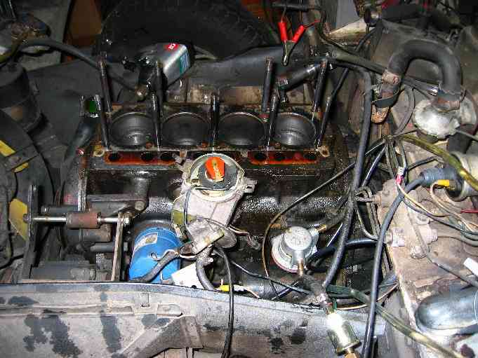
All major components removed.
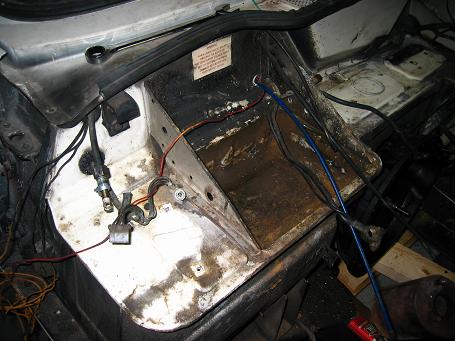
Battery well. I have owned this car for over 20 years and I never noticed the warning sticker above the battery.
This is not exactly the 9th day. Lots of short 20-30 minute sessions of painting, grinding and sanding going on. It all adds up.
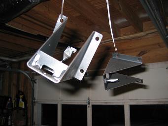
Floating Clutch and Brake Master Cylinder Brackets
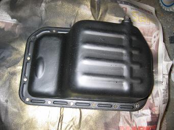
Repainted oil pan... speedbumps sure scratch up a Spitpan
I've spent the last few weeks grinding the ports on the cylinder head, getting it ready for the machine shop. I didn't grind anything too radical but did get most of the cast marks out of the intake and exhaust ports. I was worried I would ruin the valve seats the whole time I was in there, but fortunately, nothing went wrong. It isn't a professional job but it should bring about some power improvements.
Preparing the Water Pump Housing for painting.
My wife, Kim was very kind to me and the Spitfire this year... I think she wants it out of the garage :-) For Christmas, she got me the following from Spitbits:
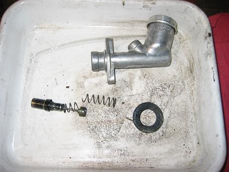
I ran into a problem with the Clutch Master Cylinder. The plunger Spring broke in two and is probably why it would not pop back out. This could be a big problem... I checked all the parts suppliers and nobody sells the spring. I may have to replace the entire Master Cylinder for lack of a 50 cent part! ARRRGH. The joy of Triumph ownership.
Merry Christmas!!
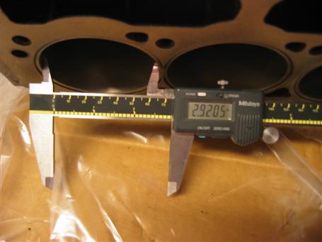
Today is the big day. I loaded up the Block, Cylinder Head and Crankshaft along with a box full of rods, bearings and valves into the Spitfire Tow Truck and drove up to Engine Rebuilders up in Trussville. These guys have done lots of British cars and they do great (CLEAN) work. The first thing they will do is a chemical bath and magnaflux. If all goes well, I'll order the size pistons and bearings they recommend. I am ordering the flat top pistons and have asked for them to skim the head to get a 9.5:1 compression ratio.. Before sending it off, I mic'ed the major dimensions:
Crankshaft
Front Main Bearing Journal - 2.3120
Center Main Bearing Journal - 2.3115
Rear Main Bearing Journal - 2.3120
Conrod #1 - 1.8765
Conrod #2 - 1.8755
Conrod #3 - 1.8750
Conrod #4 - 1.8750
Cylinder Bore
#1 - 2.8940
#2 - 2.8940
#3 - 2.8950
#4 - 2.8990
Cylinder Head Height - 3.1115
Valve Port Depth
#1 - 0.6030
#2 - 0.6035
#3 - 0.6035
#4 - 0.6035
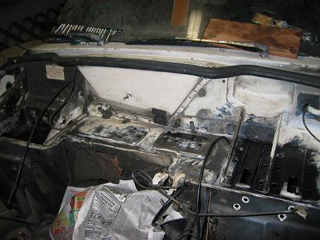
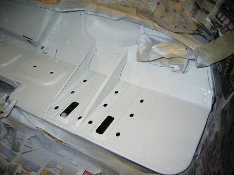
Slowly but surely, the bulkhead is taking shape. I sprayed it with Rust to Primer converter which works very well. The last time I did something like this to the Spitfire, I used Naval Jelly but I really like this spray on stuff. You can see the area around the Brake and Clutch brackets have turned black while the white paint remains white. The battery well had the most rust on the entire car and all the rust has changed to primer. Very cool stuff.
After getting some encouragement from the NASS boys, I set out to make my own spring for the Clutch Master Cylinder. I used 0.044" Music Wire from a local hobby shop and wound it around a 3/8" course thread bolt. I probably could have used one gauge down in size because the 0.044" was a bit stiffer than the original. I tried using 1/2" to start out with but the piano wire sprung out wider than 1/2". The homebrew spring fit in the cylinder but time will tell if it lasts.
.JPG)
.JPG)
Homebrew spring on top. Original on bottom.
.JPG)
Exhaust manifold painted with 1200 degree F ceramic Aluminium paint. I'm not sure how it will look on the block but it looks a lot better than the original rust. The picture doesn't capture how shiny and metallic this looks but it is really shiny. I may use this on the intake manifold and I may try it on the wheel hubs. I have some gray brake spray paint but I'll use the Aluminium paint as a primer for it if I don't like the ceramic paint.
.JPG)
I painted the brake pressure switch gold, then copper and then back to gold. I was trying to get the original brass hue and the gold comes closer than the copper paint. I did use the copper paint for the clutch hoses. That looks pretty good but my wife says I've been watching too much "Queer Eye for the Straight Guy"
.JPG)
The alternator housing has been tapped by several roadside "mechanics" in the past. I decided to strip and paint the housing. The internal components were rebuilt around 10,000 miles ago.
.JPG)
.JPG)
After weeks of rust removal, I finally laid down the first coat of primer. The primer coat is on top of two coats of rust to primer spray so the top coat should really stick. Also, in order to eliminate future paint problems from clutch/brake fluid spills, I am going to convert to silicon (DOT5) brake fluid while I have everything rebuilt. DOT 5 is supposed to be better on paint but DOT3 will remove water from the brake lines.
Well that's all for 2003. Time to head upstairs and get ready to celebrate the new year with the girls. Happy New Year, Ya'll!!!!!
Each day now consists of painting, drying, painting, drying, lather, rinse,
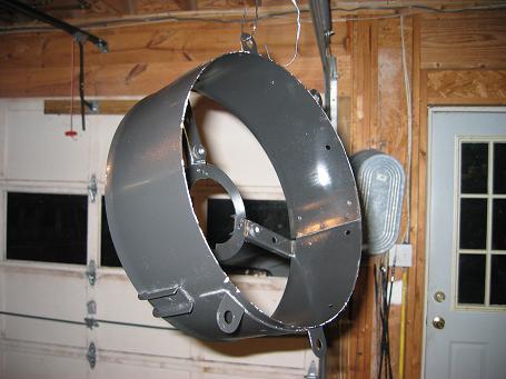
repeat. I disassembled the radiator and have painted the brackets and fan shroud.
The lower radiator hose cracked when I removed it so I have added radiator hoses
to the list of parts.
Good news from the machine shop. They called and the magnaflux results were good. They said everything looked good and told me sizes to order. So I now have .020 high-compression pistons on order as well as .010 crankshaft main and big end bearings. The parts will arrive next week and they can start machining. They really need the pistons so they can empirically measure the bore volume to determine the amount of head skimming required to get a 9.5:1 compression ratio.
Many coats of white paint.
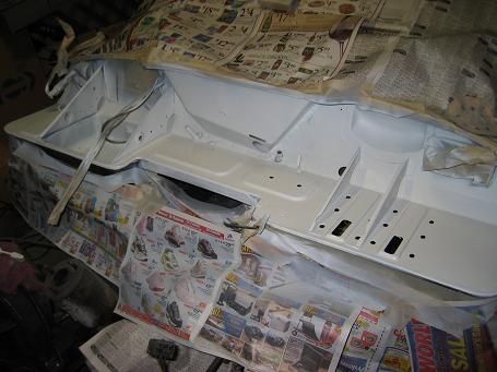
The bulkhead looks so much better than before. Other than the paint stripped by leaking clutch fluid, the bulkhead has always had smoke damage that bothered me. Back in 1983, a the week before Christmas, I ran into the mall to do a little shopping and five minutes later I was paged by name over the intercom and told to return to my vehicle. I ran back to the Spitfire to find a Fire Truck leaving my freshly hosed down engine. One of the firemen (before they were called firefighters) asked me when and where I had last filled up. I told him that I had filled up 15 minutes earlier at a gas station in Kings Mountain, NC. He told me that apparently the gas station had put leaded gasoline in their unleaded pump tanks and that they were cruising the mall parking lot going from burning car to burning car. The damage to my car was minor compared to the cars that caught fire before the Fire Department arrived. Oh... he also said that one of the firemen owned a Spitfire and knew how to open the bonnet which saved me more damage.
.JPG)
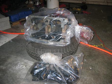
Even the tyres on my 1988 Jeep Cherokee Spitfire Tow Truck are Triumphs!!!! The Jeep has towed the Spitfire more times than I can count.
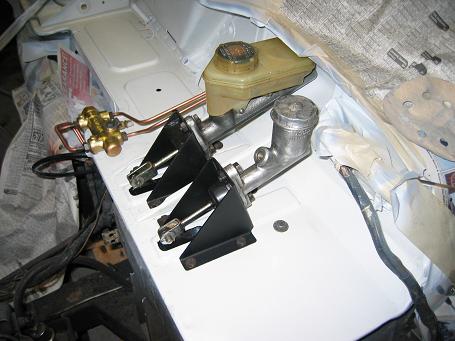
Brake and Clutch cylinders reinstalled.
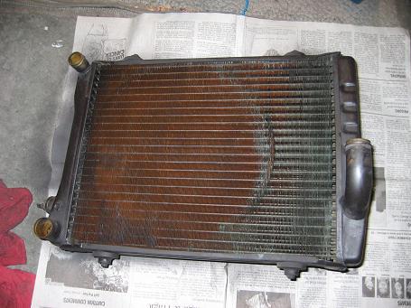
I'm going to try and salvage the radiator. The car normally ran on the warm side but didn't have the bad overheating problems that most Spitfires have.
After a three day delay due to snow, my high-compression pistons and bearings finally arrived at Mathews Foreign Car Parts. As soon as they arrived, I drove down and picked them up and delivered them to the machine shop, Engine Rebuilders. When I got there, they sifted through the box and asked where the freeze plugs where. Un fortunately, I misunderstood that they wanted me to order them but luckily, they were able to locate some that day.
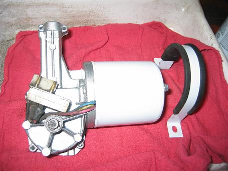
While I was waiting, I painted the wiper motor. I used metallic brake spray paint and white paint that matches the bulkhead color. The brake paint is supposed to repel dust and grease and I think it will. The paint is clear with metal flakes and looks great on top of the aluminium housing.
The newly machined engine is ready! Now the hard part begins... putting it all back together... so many parts... so little time...
Before doing anything, I decided to inspect and measure everything. Everything I have read highly recommends checking the machine shop work before doing anything. Not doing so can result in a pile of molten iron.
The cylinder head looks really nice. The cylinder head height is 3.0970 so I know the machine shop skimmed 0.0145". I won't know if that is correct amount of skimming to get 9.5:1 compression until I get it put together. I will use water to measure the volume in both the cylinders and head.
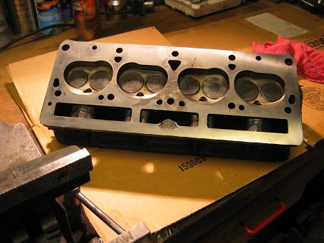
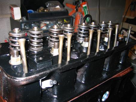
Lapped in the valves for a nice tight fit.
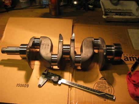
The crankshaft looks great. They turned the main and big end bearing journals down .010". My measurements show that they are spot on.
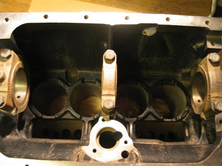
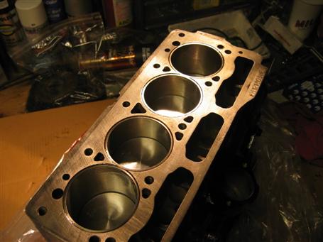
Bore diameter is +.020. According to the manual, the bore diameter is 2.9000 from the factory. All cylinders are within 0.0005 of each other.
Everything looks to be in spec so I applied Assembly Lube to the main bearings and pressed them into the block. Then I carefully lowered the crankshaft in. The Assembly Lube is great to work with. It is sticky so the bearings stay in place and it provides lubrication for the initial start up.
One of the NASS guys suggested that I check end float before applying Assembly Lube to the Thrust Washers. This was a big help because once you get the lube on, it adds thickness and makes it harder to get a feeler gauge in there.
Check the end float. 0.005 is what the shop manual calls for. Remove the Thrust Washers, lube and reinstall.
Torque the main bearings.
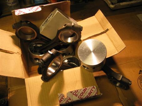
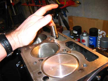
The machine shop installed the pistons on the connecting rods. These are flat tops and should give me a lot better compression.
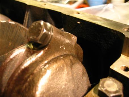
Be sure that you don't mix connecting rod bearing caps or in my case, get the rod bearing cap turned around 180 degrees. When I tightened the conrod bearings, the crank shaft would not turn. I even popped on the fly wheel to get a better grip but it still would not turn. I loosened each conrrod until I found the problem. Both #1 and #4 conrod bearing caps were turned around 180 degrees. The Bentley shop manual tells you to match up the marked ends. Note the "1" in the photo. It matches up with a "1" on the connecting rod. Once I fixed this, I could easily turn the crankshaft by hand.
All 4 pistons installed. Unfortunately, I can't mark this off the list. In reading the Bentley shop manual, they recommend replacing the connecting rod bolts. Although it doesn't make sense to me, an Electrical Engineer, I'll trust my Mechanical brethren and replace them.
The Connecting Rod Bolts arrived. It seems like a lot of money for bolts but they do take a lot of abuse. In order to keep the bearing caps straight, I removed them one at a time and immediately replaced them.
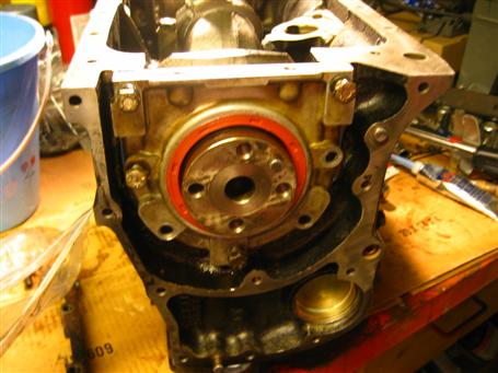
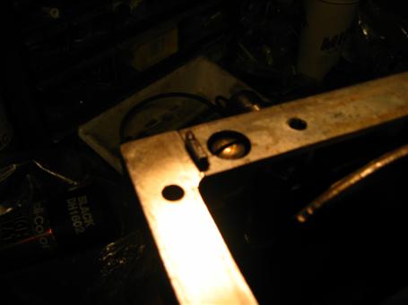
Bentley Manual Section 12.41.05 Step 42-47 Rear Oil Seal and Sealing Block fitting.
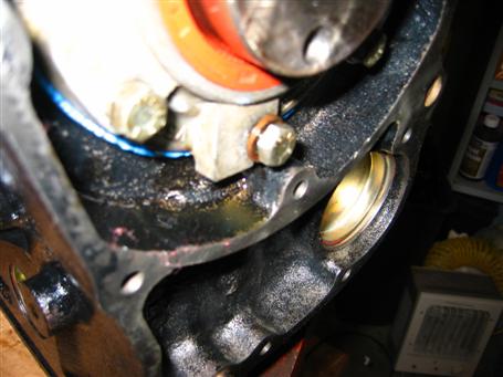
Make sure the copper washer is on the topmost screw.
Torque Sealing block to 20 ft-lbs.
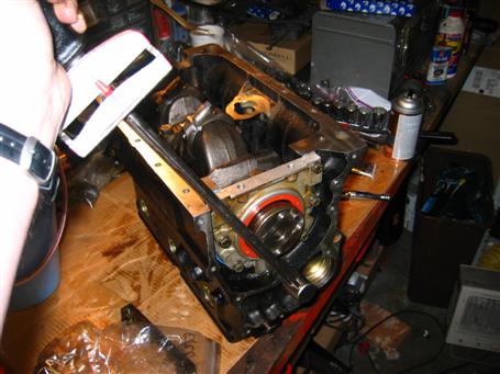
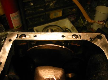
Bentley Manual Section 12.41.05 Step 48-49 Why are these wedges wooden?
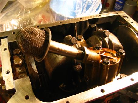
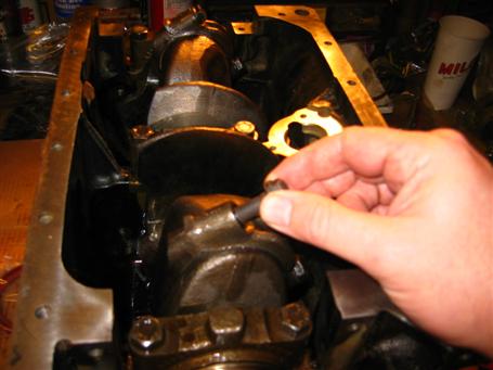
Section 12.41.05 Step 50-51 Oil Pump refitting.
Fit the oil sump and rear mounting plate
Fit Flywheel. Torque to 40 ft-lbs
Insert the new fast road camshaft.
Apply assembly lube to cam followers and insert. Per the camshaft warranty, new followers must be fitted.
Putting the head bolts back on.
Tomorrow the head gasket and head go on...
ERROR! Before putting the head back on, I decided to check the head compression empircally by measuring the volume of the combustion chamber and stroke volume. Based on some quick checks, I determined that the compression ratio was 8.3:1 which was much less than my desired 9.5:1. To take advantage of premium test, a CR of 9.3:1 or greater is required. Having paid for "Premium Test Head" and not being entirely sure if my measurements were correct I decided to do some research on compression ratios. Nobody wants to tell machinists they are wrong without having all the facts!
So for several days, I made measurements and calculations as well as asking help from NASS and TTN groups. Triumph made two version of the cylinder head; a low compression head for the US market and a high compression head for the UK. My guess is that I have the low compression head. With the original dished pistons(US), I had a CR of 7.5:1 but I will be replacing them with flat top UK pistons. The flat top piston with the low compression head must yield ~8.3:1 so I should amend my original question to ask how much I skim off a low compression head to make it into a high compression head.
To begin with, I am the second owner and bought it from the original owner with around 20k miles on it so I know that it has never had any work on it. Before I sent the head off to the machine shop, I took several key measurements. The Cylinder head height before I sent it was 3.119 and came back at 3.097 so they flattened about 12 mil off.
(There is an excellent article by John Davies called " Skimming Your Head For A Higher Compression Ratio" that is a must read. Also, check out this CR calculator )
I calculated the cylinder volume (Vcy) = h*pi*r*r
h = 8.75 cm
r = 2.920/2 = 3.7084cm
Vcy = 378.03 cc
Using a medical syringe, I measured the combustion chamber to be 48 cc.
Using the equation:
CR = ( Vcy + Vcc + Vg) / (Vcc + Vg)
Where
CR = Compression Ratio
Vcy = Cylinder volume = 378.03
Vcc = Combustion Chamber Volume = 48
Vg = Gasket Volume = 3.4
CR = ( 378.03 + 48 + 3.4 ) / ( 48 + 3.4 )
CR = 8.35:1
Solving for Combustion Chamber volume that yields 9.5:1 compression:
Vcc = (Vcy + Vg - (Vg*CR)) / (CR - 1)
Vcy = 378.03
Vg = 3.4
CR = 9.5
Vcc = 41.07
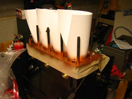
Next I added 41cc of paraffin to the combustion chamber and using a Mitutoyo micrometer, I measure roughly .050 from the top. I say roughly because it is difficult to measure against liquid. I drove back to the machine shop and had them skim .050 off. I measured the volume of th ecombustion chamber and measured about 43cc. Rather than head back to the machine shop again, I decided to err on the safe side. I'll check it with a pressure guage once I get it all put back together. If it is too far off, I'll pull the head and try again.
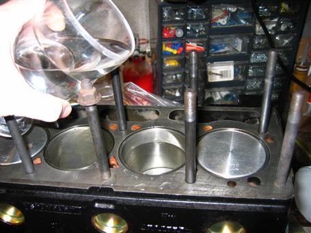
One method of measure the volume was to fill the cylinders with distilled water and weigh. 1cc = 1 gram of water.
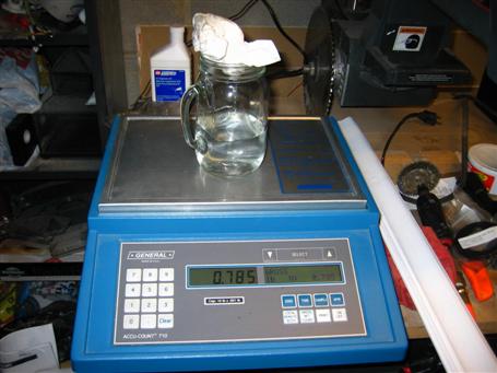
Using the weigh method, I measure 0.785 lbs = 356g = 356cc. This was off from the calculated volume so a second try and I measured 367cc, much closer to the calculated volume.
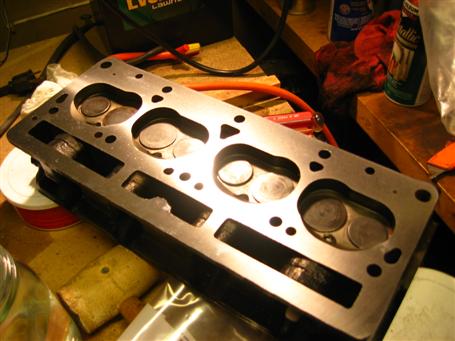
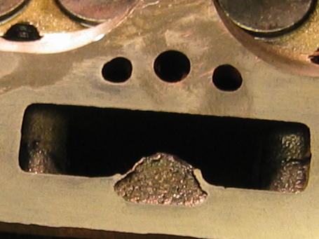
CAST MARKS BEFORE SKIMMING
Head back at home. Notice the cast marks on the face between the #2 and #3 pushrods are gone. Triumph must have been making running changes in response to the US emissions laws. I bet they just took the original head and increased the height and decided to leave the cast marks. If anyone knows or has the head height for the UK cylinder head, drop me an email at w4eae at netzero dot net(anti-spam).
I saw this trick on Paul Tegler's website and it worked great.
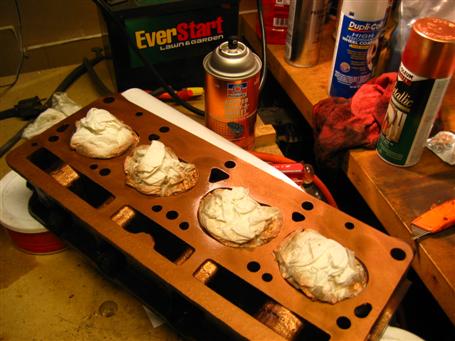
Copper gasket sealer is supposed to be better at transfering heat.
Head and Flywheel back on.
Torque the head bolts in the proper sequence.
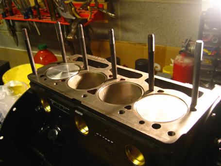
Drop in the push rods.
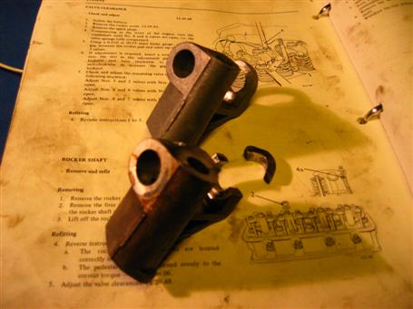
The main culprit!!! This is the rear rocker arm pedastal that broke and started this rebuild. The new one is on top.
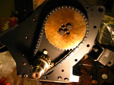
Install the new timing chain. I lined up all the score marks. Make sure you set #1 cylinder at top dead center before lining up the timing gear.
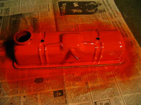
I thought I could get by without painting the valve cover but when I put it on top of the shiny new cylinder head, it looked terrible.
Distributor cap installed.
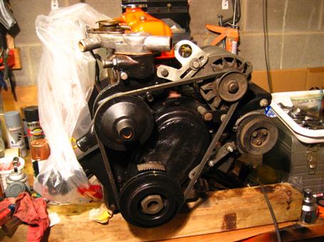
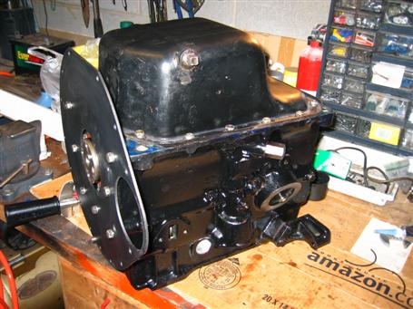
Wow.... it's beginning to look like a real engine again!!!
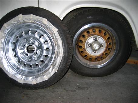
While I was waiting, I painted the rims with 1200 degree aluminum paint. They might be a little too shiny but I thought I would give it a try.
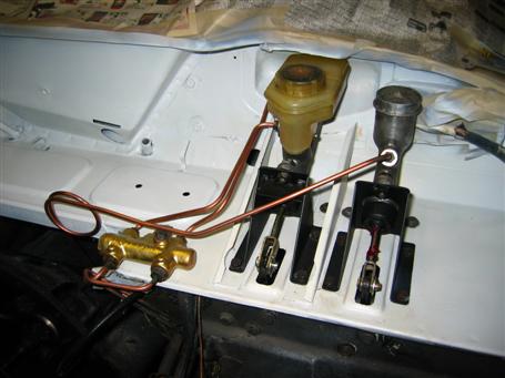
Brake and Clutch master cylinders installed and checked.
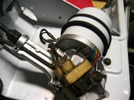
Wiper motor cleaned and painted.
Finally, it is beginning to look like the end is in sight. The engine hoist is rented so I am comitted.
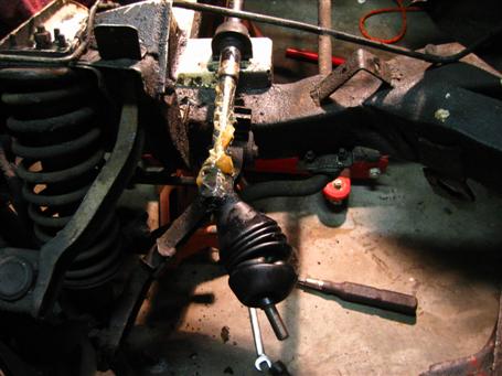
Putting on the new rack and pinion rubber boots.
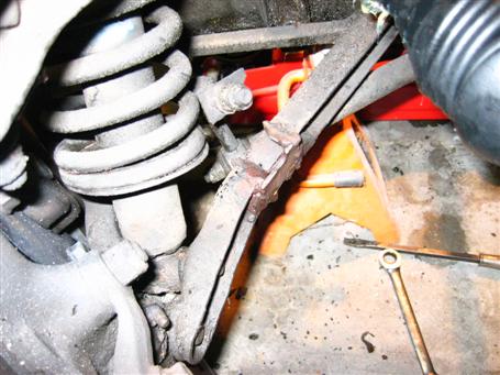
I was planning on replacing the sway bar mounts with poly but I discovered this break on the RH wishbone. Hmmm.... I can order a new one or learn how to weld...
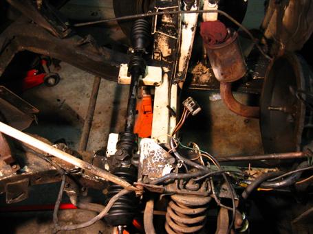
New boots!
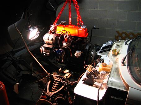
First Hour....
Second Hour...
Third Hour...
Fourth Hour.... OK.... This isn't looking good. I better ask for help.
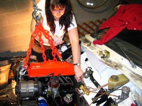
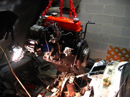
5 minutes later, Kim has the engine and transmission mated and tightens the bell housing bolts. I stand back and take pictures.
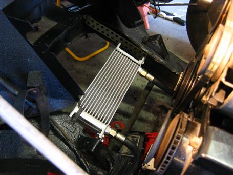
Oil Cooler installed. It seems to fit here and hopefully, the airdam will force enough air through it.
Exhaust Manifold goes on
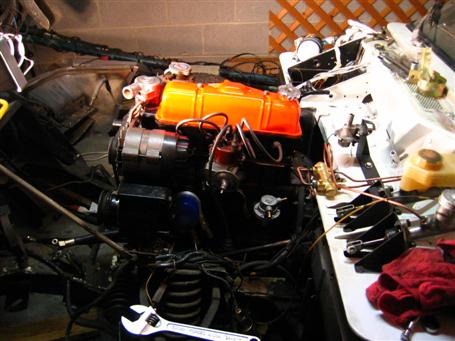
Carb and intake manifold bolted on.
Everything is back in place! All hoses and wires are hooked up and ready to go... it's 70 degrees and sunny out.... and it won't start. Gasoline drips profusely from the 150CD... Argh!!
The month of March was spent trying to get the Spitfire started. The first think I did was remove the Zentih-Stromberg 150CD carb. Upon inspection, I found a screw missing that held the choke housing. The gasket around it was blown so I ordered a new screw and rebuild kit. After rebuilding the 150CD, I was getting too much gas fouling the plugs. A fellow NASSer, RazorBob Arnett sold me his Weber DGV. I replaced the 150CD with the Weber and the engine continued to turn without firing. I checked the plugd and they were bone dry so I was suspecting timing... I should have stopped here and thought about the wet plugs from the 150CD but I didn't.
Next, I checked the camshaft timing. Everything seemed to check out and the timing looked correct. A long-time Triumph mechanic had suggested that I arrange the oil spithole to match the drawing in the shop manual. So I pulled off the timing gear cover and pulled the sprocket and the spithole was 180 degrees out from the drawing so I pulled it and turned it to match the drawing. (Before you change your camshaft let me tell you that this was wrong for my particular cam shaft.) I bolted the timing gear cover back on and she still wouldn't start. The picture above shows me pushing rope into the sparkplug holes so I can get enough torque on the crankshaft flywheel nut.
By this time, depression sets in... I let it sit for a week while I contemplated the next course of action. I remembered Bob warning me that he had to grind metal to get the intake manifold to fit with the heat shield. I had not installed the heat shield because of this but I began to wonder if maybe there was interference between the intake and exhaust manifolds. So I removed the intake mannifold and sure enough there was gasket sealant on the top edge but not on the bottom edge. I refit the intake manifiold and tried to slide a piece of paper between the intake and exhaust manifold and it wouldn't go. So I pulled out my trusty grinder and ground away at the exhaust manifold until I could fit a piece of paper and then cardboard between the manifolds. I cranked the engine but still no combustion. I pulled the plugs and they were slightly moist so I had fixed a manifold leak. one problem down and who knows how many more to go...
I met Dave Lambert on the NASS list and found out that he lived in the same town. He had raced autocross and was looking at building a Spitfire autocrosser and offered to stop by and help me get her started. We tried all kinds of tricks but still no combustion. Dave thought that the plugs should be completely fouled and flooded with all the cranking so he dropped th bowl on the Weber and found a stuck float. He put it back together and we tried to crank it. Still no combustion but now the smell of flooding and fouled plugs told us that we had fixed another problem... one more down... more to go...
I spoke with another mechanic who had rebuilt lots of engines and he suggested that I check the compression. He said I should see 60 or more psi to get enough compression for a succesful compression stroke. He said that he had rebuilt engines with low compression before the rings were properly set. He told me that an old mechanics trick was to pour oil through the sparkplug holes to seal the rings long enough to get a compression and hopefully get the rings set. I connected my compression gauge to each cylinder and they all ranged around 20 psi. I tried the oil trick and the compressionshot up to 100 but quickly dropped to 50 and the to 20 psi again. Oh and still no combustion....
By this time, I decided to call in the cavalry and get Paul Gardner to look at it. Paul worked as a mechnic at the local British Leyland dealership up until 1980 (R.I.P) when he went independent and opened his own shop. Hopefully, it was a simple cockpit error and he would find it in quickly. I prepped the Spitfire for its first outside excursion in five years. The rear window was a nice dingy yellow... another thing to replace...
I called Paul in the morning to find out how things were going. He said he removed the timing gear cover and said that the camshaft was 180 degrees out and that I had it correct the first time. Hopefully that was all that was wrong and she should start up after he got the timing gear cover back on.
Good News and Questions....
Paul called tonight and had some good news... kind of... He told me the good news was that I didn't do anything wrong but he had some questions. He asked me if the rings came installed on the pistons. I told him that the rings came in a separate box in with the box of pistons. Fortunately, I had kept the boxes and reciepts and read the part numbers off to him. Sure enough, it appeared that the rings seemed suspect. He determined this by removing the oil pan and pouring oil in the sparkplug hole. When he cranked it he said that the oil was blowing out the bottom. He also said the gap between the rings and cylinder walls was bigger than it should be.
Next he pulled the cylinder head and pulled one of the pistons and confirmed his suspision that the rings were incorrect, or as he put it, "like rings on a riding lawn mower." He said that the he uses the supplier all the time and that they will make things right.
The next step is to tow the Spitfire back home and replace the rings. I will do this without pulling the engine so it should make for some interesting photos. Stay tuned...
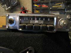
I listen to my British Leyland Radio while I wait...
Spitfire Arrives home.
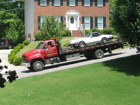
Report to follow with detailed photos...
SUCCESS!!!! The beautiful sound of my rebuilt 1500 playing through fine Italian Ansa Exhausts!
.jpg)
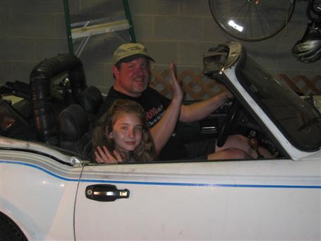
The maiden voyage! The last Spitfire trip was seven years ago while driving my daughter Megan to the store. She was in a small carseat then but she's all grown up now.
We head to out to the end of the driveway....
...and SUCCESS! We return!

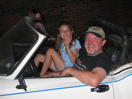
And Gillian goes for a ride. She has never seen the Spitfire move out of the garage!
Click here to go to the Birmingham British Motoring Club Car Show 2004
Click here to Download Zenith Stromberg Heat Shield Drawing
Click here to Download 1:1 Scale Heatshield Drawing
e mail me at w4eae at netzero dot net
All material and images Copyright 2004 Gene Eighmy
|
||||||